Suppose You Have Your Father's 3.75 D Reading Glasses How Far From a Piece of Paper Must
Learning Objectives
Past the terminate of this section, y'all will be able to:
- Listing the rules for ray tracking for sparse lenses.
- Illustrate the germination of images using the technique of ray tracking.
- Determine ability of a lens given the focal length.
Lenses are establish in a huge array of optical instruments, ranging from a uncomplicated magnifying glass to the center to a camera's zoom lens. In this section, we volition utilise the law of refraction to explore the properties of lenses and how they form images.
The word lens derives from the Latin give-and-take for a lentil bean, the shape of which is similar to the convex lens in Figure 1. The convex lens shown has been shaped so that all light rays that enter information technology parallel to its centrality cross ane some other at a single point on the opposite side of the lens. (The axis is defined to exist a line normal to the lens at its center, as shown in Effigy 1.) Such a lens is called a converging (or convex) lens for the converging effect it has on light rays. An expanded view of the path of one ray through the lens is shown, to illustrate how the ray changes direction both as information technology enters and as it leaves the lens. Since the index of refraction of the lens is greater than that of air, the ray moves towards the perpendicular as it enters and away from the perpendicular as it leaves. (This is in accordance with the law of refraction.) Due to the lens'due south shape, low-cal is thus aptitude toward the axis at both surfaces. The point at which the rays cantankerous is defined to be the focal point F of the lens. The altitude from the center of the lens to its focal point is defined to exist the focal length f of the lens. Effigy 2 shows how a converging lens, such as that in a magnifying glass, can converge the nearly parallel calorie-free rays from the sun to a small-scale spot.

Figure 1. Rays of light entering a converging lens parallel to its axis converge at its focal point F. (Ray two lies on the axis of the lens.) The altitude from the heart of the lens to the focal indicate is the lens's focal length f. An expanded view of the path taken by ray 1 shows the perpendiculars and the angles of incidence and refraction at both surfaces.
Converging or Convex Lens
The lens in which light rays that enter it parallel to its axis cross one another at a unmarried signal on the opposite side with a converging effect is called converging lens.
Focal Signal F
The point at which the light rays cantankerous is called the focal point F of the lens.
Focal Length f
The distance from the center of the lens to its focal indicate is called focal length f.

Effigy 2. Sunlight focused by a converging magnifying glass can burn paper. Low-cal rays from the sun are nearly parallel and cantankerous at the focal point of the lens. The more powerful the lens, the closer to the lens the rays volition cross.
The greater effect a lens has on light rays, the more powerful information technology is said to exist. For example, a powerful converging lens volition focus parallel lite rays closer to itself and will accept a smaller focal length than a weak lens. The light will also focus into a smaller and more than intense spot for a more powerful lens. The power P of a lens is defined to be the inverse of its focal length. In equation form, this is [latex]P=\frac{1}{f}\\[/latex].
Power P
The ability P of a lens is defined to exist the inverse of its focal length. In equation form, this is [latex]P=\frac{1}{f}\\[/latex], where f is the focal length of the lens, which must exist given in meters (and not cm or mm). The ability of a lens P has the unit diopters (D), provided that the focal length is given in meters. That is, [latex]one\text{D}=\frac{1}{\text{m}}\text{, or }ane\text{m}^{-ane}\\[/latex]. (Note that this ability (optical power, really) is not the same as power in watts defined in the chapter Work, Energy, and Energy Resources. It is a concept related to the upshot of optical devices on low-cal.) Optometrists prescribe common glasses and contact lenses in units of diopters.
Example 1. What is the Power of a Common Magnifying Glass?
Suppose you take a magnifying glass out on a sunny day and you observe that it concentrates sunlight to a pocket-sized spot eight.00 cm away from the lens. What are the focal length and power of the lens?
Strategy
The situation here is the same as those shown in Effigy 1 and Effigy two. The Sun is then far away that the Lord's day'southward rays are nearly parallel when they reach Globe. The magnifying glass is a convex (or converging) lens, focusing the virtually parallel rays of sunlight. Thus the focal length of the lens is the altitude from the lens to the spot, and its power is the inverse of this altitude (in m).
Solution
The focal length of the lens is the distance from the center of the lens to the spot, given to be 8.00 cm. Thus,
f= viii.00 cm.
To detect the power of the lens, nosotros must beginning catechumen the focal length to meters; then, we substitute this value into the equation for power. This gives
[latex]P=\frac{i}{f}=\frac{1}{0.0800\text{ chiliad}}=12.5\text{ D}\\[/latex].
Discussion
This is a relatively powerful lens. The power of a lens in diopters should not exist confused with the familiar concept of ability in watts. It is an unfortunate fact that the word "power" is used for two completely unlike concepts. If you examine a prescription for eyeglasses, y'all volition annotation lens powers given in diopters. If yous examine the label on a motor, yous will annotation energy consumption rate given as a power in watts.

Figure 3. Rays of light inbound a diverging lens parallel to its axis are diverged, and all appear to originate at its focal point F. The dashed lines are not rays—they indicate the directions from which the rays appear to come. The focal length f of a diverging lens is negative. An expanded view of the path taken by ray i shows the perpendiculars and the angles of incidence and refraction at both surfaces.
Figure iii shows a concave lens and the effect it has on rays of lite that enter it parallel to its centrality (the path taken past ray 2 in the Effigy is the axis of the lens). The concave lens is a diverging lens, considering it causes the light rays to bend abroad (diverge) from its axis. In this example, the lens has been shaped so that all light rays entering information technology parallel to its centrality announced to originate from the same point, F, defined to exist the focal point of a diverging lens. The distance from the center of the lens to the focal indicate is once again called the focal length f of the lens. Notation that the focal length and power of a diverging lens are defined to be negative.
For example, if the distance to F in Effigy three is v.00 cm, then the focal length is f = –5.00 cm and the power of the lens is P = –20 D. An expanded view of the path of ane ray through the lens is shown in the Figure to illustrate how the shape of the lens, together with the law of refraction, causes the ray to follow its particular path and be diverged.
Diverging Lens
A lens that causes the calorie-free rays to bend away from its axis is called a diverging lens.
As noted in the initial discussion of the law of refraction in The Police force of Refraction, the paths of light rays are exactly reversible. This means that the direction of the arrows could be reversed for all of the rays in Effigy ane and Figure iii. For example, if a point low-cal source is placed at the focal betoken of a convex lens, equally shown in Figure four, parallel lite rays emerge from the other side.

Figure four. A modest light source, like a light bulb filament, placed at the focal betoken of a convex lens, results in parallel rays of light emerging from the other side. The paths are exactly the reverse of those shown in Figure one. This technique is used in lighthouses and sometimes in traffic lights to produce a directional beam of light from a source that emits lite in all directions.
Ray Tracing and Thin Lenses
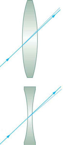
Figure 6. The calorie-free ray through the center of a thin lens is deflected by a negligible amount and is assumed to emerge parallel to its original path (shown as a shaded line).
Ray tracing is the technique of determining or following (tracing) the paths that light rays take. For rays passing through matter, the law of refraction is used to trace the paths. Here nosotros use ray tracing to assist us empathize the action of lenses in situations ranging from forming images on film to magnifying small print to correcting nearsightedness. While ray tracing for complicated lenses, such as those found in sophisticated cameras, may require estimator techniques, at that place is a set of simple rules for tracing rays through thin lenses.
A thin lens is defined to be one whose thickness allows rays to refract, as illustrated in Effigy one, simply does not allow backdrop such as dispersion and aberrations. An ideal thin lens has two refracting surfaces but the lens is sparse enough to presume that light rays curve only in one case. A thin symmetrical lens has two focal points, 1 on either side and both at the same distance from the lens. (See Figure six.)
Some other important characteristic of a thin lens is that light rays through its center are deflected by a negligible amount, as seen in Figure 5.
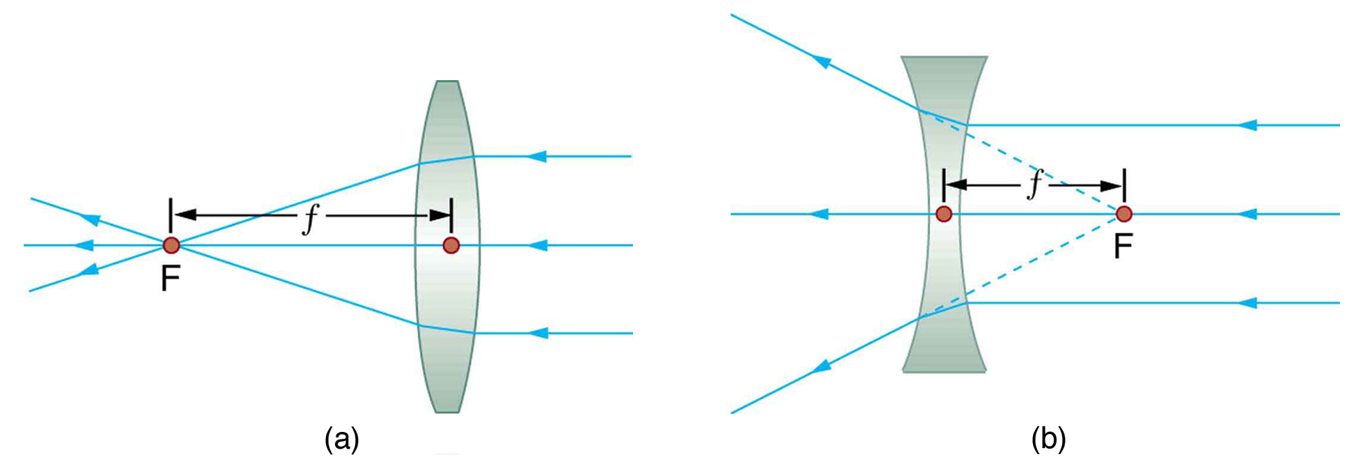
Effigy 6. Sparse lenses accept the same focal length on either side. (a) Parallel low-cal rays entering a converging lens from the right cross at its focal point on the left. (b) Parallel light rays entering a diverging lens from the right seem to come from the focal bespeak on the right.
Thin Lens
A thin lens is defined to be i whose thickness allows rays to refract merely does not allow properties such as dispersion and aberrations.
Take-Home Experiment: A Visit to the Optician
Await through your eyeglasses (or those of a friend) astern and frontward and comment on whether they act like sparse lenses.
Using newspaper, pencil, and a straight border, ray tracing can accurately describe the operation of a lens. The rules for ray tracing for thin lenses are based on the illustrations already discussed:
- A ray entering a converging lens parallel to its axis passes through the focal point F of the lens on the other side. (See rays i and 3 in Effigy 1.)
- A ray entering a diverging lens parallel to its centrality seems to come from the focal betoken F. (See rays 1 and 3 in Figure 2.)
- A ray passing through the heart of either a converging or a diverging lens does non change direction. (Run across Effigy 5, and see ray 2 in Figure one and Figure two.)
- A ray entering a converging lens through its focal point exits parallel to its centrality. (The contrary of rays one and three in Figure 1.)
- A ray that enters a diverging lens past heading toward the focal betoken on the opposite side exits parallel to the centrality. (The opposite of rays i and iii in Figure ii.)
Rules for Ray Tracing
- A ray entering a converging lens parallel to its centrality passes through the focal point F of the lens on the other side.
- A ray inbound a diverging lens parallel to its axis seems to come up from the focal indicate F.
- A ray passing through the center of either a converging or a diverging lens does not change management.
- A ray entering a converging lens through its focal point exits parallel to its axis.
- A ray that enters a diverging lens by heading toward the focal point on the reverse side exits parallel to the axis.
Prototype Germination by Thin Lenses
In some circumstances, a lens forms an obvious image, such as when a movie projector casts an paradigm onto a screen. In other cases, the prototype is less obvious. Where, for example, is the image formed by eyeglasses? We will employ ray tracing for thin lenses to illustrate how they class images, and nosotros volition develop equations to describe the paradigm germination quantitatively.

Figure 7. Ray tracing is used to locate the image formed by a lens. Rays originating from the same betoken on the object are traced—the three called rays each follow i of the rules for ray tracing, so that their paths are like shooting fish in a barrel to determine. The paradigm is located at the signal where the rays cantankerous. In this case, a real image—one that tin be projected on a screen—is formed.
Consider an object some distance away from a converging lens, equally shown in Figure 7. To find the location and size of the image formed, nosotros trace the paths of selected light rays originating from one point on the object, in this case the top of the person'southward head. The Figure shows iii rays from the top of the object that can be traced using the ray tracing rules given above. (Rays go out this point going in many directions, but we concentrate on just a few with paths that are easy to trace.) The outset ray is one that enters the lens parallel to its axis and passes through the focal signal on the other side (rule 1). The 2nd ray passes through the center of the lens without irresolute management (rule 3). The third ray passes through the nearer focal point on its manner into the lens and leaves the lens parallel to its axis (rule 4). The three rays cross at the same bespeak on the other side of the lens. The image of the height of the person's head is located at this signal. All rays that come from the same point on the tiptop of the person's head are refracted in such a way equally to cross at the point shown. Rays from another point on the object, such as her chugalug buckle, volition also cross at another common point, forming a complete paradigm, every bit shown. Although iii rays are traced in Figure 7, only 2 are necessary to locate the image. It is all-time to trace rays for which there are elementary ray tracing rules. Earlier applying ray tracing to other situations, let united states of america consider the example shown in Effigy 7 in more detail.
The image formed in Figure 7 is a real prototype, meaning that information technology tin can be projected. That is, lite rays from 1 point on the object really cantankerous at the location of the paradigm and can exist projected onto a screen, a piece of film, or the retina of an center, for example. Figure 8 shows how such an image would exist projected onto film past a photographic camera lens. This Figure also shows how a real image is projected onto the retina by the lens of an eye. Notation that the paradigm is at that place whether it is projected onto a screen or not.
Real Paradigm
The image in which light rays from one point on the object really cantankerous at the location of the prototype and tin can exist projected onto a screen, a piece of film, or the retina of an eye is called a real image.

Effigy eight. Real images can be projected. (a) A existent image of the person is projected onto pic. (b) The converging nature of the multiple surfaces that make up the eye consequence in the projection of a real epitome on the retina.
Several important distances appear in Figure 7. Nosotros define d o to be the object distance, the distance of an object from the middle of a lens. Image distance d i is defined to be the distance of the paradigm from the center of a lens. The summit of the object and height of the paradigm are given the symbols h o and h i, respectively. Images that announced upright relative to the object have heights that are positive and those that are inverted accept negative heights. Using the rules of ray tracing and making a calibration drawing with paper and pencil, similar that in Figure 7, we can accurately depict the location and size of an image. But the real benefit of ray tracing is in visualizing how images are formed in a variety of situations. To obtain numerical data, we use a pair of equations that can exist derived from a geometric assay of ray tracing for thin lenses. The thin lens equations are
[latex]\frac{1}{d_\text{o}}+\frac{1}{d_{\text{i}}}=\frac{1}{f}\\[/latex] and [latex]\frac{h_{\text{i}}}{h_\text{o}}=\frac{d_{\text{i}}}{d_{\text{o}}}=g\\[/latex].
We define the ratio of image tiptop to object meridian [latex]\left(\frac{h_{\text{i}}}{h_\text{o}}\right)\\[/latex] to be the magnification m. (The minus sign in the equation higher up will be discussed shortly.) The sparse lens equations are broadly applicative to all situations involving thin lenses (and "thin" mirrors, every bit we will see later). Nosotros will explore many features of image formation in the following worked examples.
Image Distance
The distance of the prototype from the center of the lens is called image altitude.
Thin Lens Equations and Magnification
[latex]\displaystyle\frac{one}{d_\text{o}}+\frac{i}{d_{\text{i}}}=\frac{1}{f}\\[/latex]
[latex]\displaystyle\frac{h_{\text{i}}}{h_\text{o}}=\frac{d_{\text{i}}}{d_{\text{o}}}=m\\[/latex]
Example ii. Finding the Prototype of a Lite Seedling Filament by Ray Tracing and by the Thin Lens Equations
A clear glass light seedling is placed 0.750 m from a convex lens having a 0.500 m focal length, every bit shown in Figure nine. Use ray tracing to get an approximate location for the paradigm. Then apply the sparse lens equations to calculate both the location of the image and its magnification. Verify that ray tracing and the thin lens equations produce consistent results.

Effigy 9. A light bulb placed 0.750 yard from a lens having a 0.500 m focal length produces a real image on a poster lath equally discussed in the example higher up. Ray tracing predicts the image location and size.
Strategy and Concept
Since the object is placed further abroad from a converging lens than the focal length of the lens, this situation is analogous to those illustrated in Figure vii and Figure eight. Ray tracing to calibration should produce similar results for d i. Numerical solutions for d i and m can be obtained using the sparse lens equations, noting thatd o = 0.750 thousand andf = 0.500 m.
Solutions (Ray Tracing)
The ray tracing to scale in Figure 9 shows two rays from a point on the seedling's filament crossing about 1.50 m on the far side of the lens. Thus the prototype distance d i is well-nigh i.l m. Similarly, the paradigm meridian based on ray tracing is greater than the object tiptop by about a factor of 2, and the image is inverted. Thus m is well-nigh –ii. The minus sign indicates that the image is inverted.
The sparse lens equations can exist used to find d i from the given information:
[latex]\frac{i}{d_\text{o}}+\frac{one}{d_{\text{i}}}=\frac{1}{f}\\[/latex].
Rearranging to isolate d i gives
[latex]\frac{1}{d_{\text{i}}}=\frac{1}{f}-\frac{1}{d_\text{o}}\\[/latex].
Inbound known quantities gives a value for[latex]\frac{1}{d_{\text{i}}}\\[/latex]:
[latex]\frac{1}{d_{\text{i}}}=\frac{i}{0.500\text{ m}}-\frac{i}{0.750\text{ 1000}}=\frac{0.667}{\text{m}}\\[/latex].
This must be inverted to find d i:
[latex]d_{\text{i}}=\frac{\text{m}}{0.667}=1.50\text{ thousand}\\[/latex].
Note that another fashion to find d i is to rearrange the equation:
[latex]\frac{1}{d_\text{i}}=\frac{1}{f}-\frac{1}{d_{\text{o}}}\\[/latex].
This yields the equation for the image altitude equally:
[latex]d_{\text{i}}=\frac{fd_{\text{o}}}{d_{\text{o}}-f}\\[/latex]
Note that at that place is no inverting here.
The thin lens equations can be used to find the magnification one thousand, since both d i and d o are known. Entering their values gives
[latex]\displaystyle{m}=-\frac{d_{\text{i}}}{d_{\text{o}}}=-\frac{one.fifty\text{ k}}{0.750\text{ one thousand}}=-2.00\\[/latex]
Discussion
Note that the minus sign causes the magnification to be negative when the image is inverted. Ray tracing and the use of the thin lens equations produce consistent results. The thin lens equations give the most precise results, being limited only by the accuracy of the given information. Ray tracing is express by the accuracy with which yous can draw, but it is highly useful both conceptually and visually.
Real images, such as the ane considered in the previous example, are formed by converging lenses whenever an object is farther from the lens than its focal length. This is true for moving-picture show projectors, cameras, and the eye. We shall refer to these as instance 1 images. A example one prototype is formed when d o >f and f is positive, as in Figure 10a. (A summary of the three cases or types of prototype formation appears at the end of this section.)
A different type of epitome is formed when an object, such as a person'southward face up, is held close to a convex lens. The paradigm is upright and larger than the object, as seen in Figure 10b, and so the lens is called a magnifier. If you lot slowly pull the magnifier abroad from the face, you will run into that the magnification steadily increases until the image begins to blur. Pulling the magnifier even farther away produces an inverted prototype as seen in Figure 10a. The distance at which the image blurs, and beyond which it inverts, is the focal length of the lens. To use a convex lens as a magnifier, the object must exist closer to the converging lens than its focal length. This is chosen a case ii prototype. A example two image is formed when d o <f and f is positive.
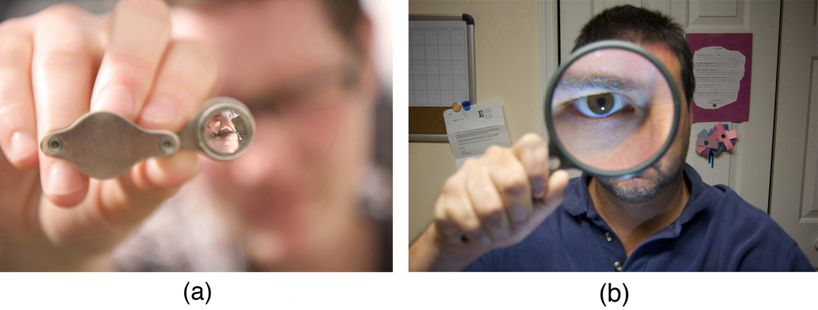
Effigy ten. (a) When a converging lens is held farther away from the face up than the lens'southward focal length, an inverted image is formed. This is a case i epitome. Note that the epitome is in focus only the face is not, because the epitome is much closer to the photographic camera taking this photograph than the confront. (credit: DaMongMan, Flickr) (b) A magnified paradigm of a face is produced by placing information technology closer to the converging lens than its focal length. This is a example 2 image. (credit: Casey Fleser, Flickr)

Figure 11. Ray tracing predicts the image location and size for an object held closer to a converging lens than its focal length. Ray 1 enters parallel to the axis and exits through the focal point on the opposite side, while ray 2 passes through the center of the lens without irresolute path. The two rays go on to diverge on the other side of the lens, only both announced to come from a common bespeak, locating the upright, magnified, virtual image. This is a instance 2 image.
Figure 11 uses ray tracing to show how an image is formed when an object is held closer to a converging lens than its focal length. Rays coming from a common point on the object continue to diverge after passing through the lens, just all appear to originate from a point at the location of the image. The image is on the same side of the lens equally the object and is farther away from the lens than the object. This prototype, like all instance 2 images, cannot be projected and, hence, is called a virtual image.
Light rays but announced to originate at a virtual paradigm; they do not actually laissez passer through that location in space. A screen placed at the location of a virtual image will receive only lengthened light from the object, not focused rays from the lens. Additionally, a screen placed on the contrary side of the lens will receive rays that are still diverging, then no prototype will be projected on it. We can see the magnified paradigm with our eyes, considering the lens of the eye converges the rays into a real image projected on our retina. Finally, we annotation that a virtual prototype is upright and larger than the object, meaning that the magnification is positive and greater than 1.
Virtual Image
An prototype that is on the same side of the lens as the object and cannot be projected on a screen is chosen a virtual image.
Case three. Image Produced by a Magnifying Glass
Suppose the book folio in Figure 11a is held seven.50 cm from a convex lens of focal length 10.0 cm, such as a typical magnifying glass might have. What magnification is produced?
Strategy and Concept
We are given that d o = vii.50 cm and f= 10.0 cm, and so we take a situation where the object is placed closer to the lens than its focal length. Nosotros therefore await to get a case 2 virtual epitome with a positive magnification that is greater than i. Ray tracing produces an image similar that shown in Effigy 11, but nosotros volition use the sparse lens equations to get numerical solutions in this example.
Solution
To discover the magnification m, we try to employ magnification equation, [latex]m=-\frac{d_{\text{i}}}{d_{\text{o}}}\\[/latex]. We do not have a value for d i, so that we must first find the location of the image using lens equation. (The process is the aforementioned as followed in the preceding case, where d o and f were known.) Rearranging the magnification equation to isolate d i gives
[latex]\frac{1}{d_\text{i}}=\frac{ane}{f}-\frac{i}{d_{\text{o}}}\\[/latex].
Inbound known values, we obtain a value for [latex]\frac{1}{d_\text{i}}\\[/latex]:
[latex]\frac{1}{d_\text{i}}=\frac{i}{x.0\text{ cm}}-\frac{1}{vii.50\text{ cm}}=\frac{-0.0333}{\text{cm}}\\[/latex].
This must be inverted to find d i:
[latex]d_{\text{i}}=-\frac{\text{cm}}{0.0333}=-30.0\text{ cm}\\[/latex].
Now the thin lens equation tin exist used to find the magnification m, since both d i and d o are known. Entering their values gives
[latex]\displaystyle{k}=-\frac{d_{\text{i}}}{d_{\text{o}}}=-\frac{-30.0\text{ cm}}{ten.0\text{ cm}}=3.00\\[/latex]
Give-and-take
A number of results in this example are true of all instance two images, as well as beingness consistent with Figure 11. Magnification is indeed positive (equally predicted), meaning the image is upright. The magnification is also greater than i, significant that the paradigm is larger than the object—in this case, by a factor of three. Note that the paradigm distance is negative. This means the epitome is on the same side of the lens as the object. Thus the image cannot be projected and is virtual. (Negative values of d i occur for virtual images.) The image is farther from the lens than the object, since the image altitude is greater in magnitude than the object altitude. The location of the image is not obvious when you look through a magnifier. In fact, since the prototype is bigger than the object, you may retrieve the epitome is closer than the object. Merely the image is farther away, a fact that is useful in correcting farsightedness, equally we shall see in a later section.

Figure 12. A car viewed through a concave or diverging lens looks upright. This is a instance 3 paradigm. (credit: Daniel Oines, Flickr)
A third type of paradigm is formed past a diverging or concave lens. Try looking through eyeglasses meant to correct nearsightedness. (Run across Figure 12.) You volition run into an image that is upright merely smaller than the object. This means that the magnification is positive just less than ane. The ray diagram in Effigy 13 shows that the epitome is on the aforementioned side of the lens equally the object and, hence, cannot be projected—it is a virtual paradigm. Note that the epitome is closer to the lens than the object. This is a example 3 paradigm, formed for whatsoever object by a negative focal length or diverging lens.

Figure 13. Ray tracing predicts the image location and size for a concave or diverging lens. Ray 1 enters parallel to the centrality and is aptitude so that it appears to originate from the focal betoken. Ray 2 passes through the center of the lens without changing path. The two rays announced to come from a common point, locating the upright image. This is a case 3 paradigm, which is closer to the lens than the object and smaller in height.
Example iv. Prototype Produced by a Concave Lens
Suppose an object such as a volume page is held 7.50 cm from a concave lens of focal length –10.0 cm. Such a lens could be used in eyeglasses to right pronounced nearsightedness. What magnification is produced?
Strategy and Concept
This example is identical to the preceding 1, except that the focal length is negative for a concave or diverging lens. The method of solution is thus the same, but the results are dissimilar in of import ways.
Solution
To detect the magnification m, we must start find the image distance d i using thin lens equation [latex]\frac{ane}{d_\text{i}}=\frac{ane}{f}-\frac{1}{d_{\text{o}}}\\[/latex], or its alternative rearrangement [latex]{d_\text{i}}=\frac{fd_{\text{o}}}{d_{\text{o}}-f}\\[/latex].
We are given that f= –ten.0 cm and d o= 7.l cm. Entering these yields a value for [latex]\frac{i}{d_{\text{i}}}\\[/latex]:
[latex]\displaystyle\frac{ane}{d_{\text{i}}}=\frac{one}{-x.0\text{ cm}}-\frac{1}{seven.50\text{ cm}}=\frac{-0.2333}{\text{cm}}\\[/latex]
This must be inverted to detect d i:
[latex]\displaystyle{d_\text{i}}=-\frac{\text{cm}}{0.2333}=-4.29\text{ cm}\\[/latex]
Or
[latex]\displaystyle{d}_{\text{i}}=\frac{\left(7.5\right)\left(-10\right)}{\left(7.5-\left(-10\right)\right)}=-\frac{75}{17.5}=-four.29\text{ cm}\\[/latex]
At present the magnification equation can be used to detect the magnification m, since both d i and d o are known. Entering their values gives
[latex]\displaystyle{m}=-\frac{d_{\text{i}}}{d_{\text{o}}}=-\frac{-4.29\text{ cm}}{7.50\text{ cm}}=0.571\\[/latex]
Discussion
A number of results in this example are truthful of all case 3 images, too as existence consistent with Figure 13. Magnification is positive (as predicted), meaning the epitome is upright. The magnification is too less than 1, meaning the epitome is smaller than the object—in this case, a little over half its size. The paradigm distance is negative, meaning the image is on the aforementioned side of the lens equally the object. (The image is virtual.) The image is closer to the lens than the object, since the image altitude is smaller in magnitude than the object altitude. The location of the image is non obvious when you lot await through a concave lens. In fact, since the image is smaller than the object, yous may think it is farther abroad. But the image is closer than the object, a fact that is useful in correcting nearsightedness, as nosotros shall see in a afterward section.
Table ane summarizes the three types of images formed past single thin lenses. These are referred to as case 1, 2, and three images. Convex (converging) lenses can grade either real or virtual images (cases 1 and 2, respectively), whereas concave (diverging) lenses tin grade only virtual images (e'er case three). Existent images are always inverted, but they can be either larger or smaller than the object. For example, a slide projector forms an epitome larger than the slide, whereas a camera makes an epitome smaller than the object being photographed. Virtual images are always upright and cannot be projected. Virtual images are larger than the object only in example 2, where a convex lens is used. The virtual image produced by a concave lens is always smaller than the object—a case three image. Nosotros can run across and photograph virtual images only by using an boosted lens to class a real image.
| Table 1. Three Types of Images Formed By Thin Lenses | ||||
|---|---|---|---|---|
| Type | Formed when | Paradigm type | d i | m |
| Case 1 | f positive, d o>f | real | positive | negative |
| Example ii | f positive, d o<f | virtual | negative | positive chiliad > 1 |
| Instance 3 | f negative | virtual | negative | positive m < one |
In Image Formation past Mirrors, nosotros shall encounter that mirrors can grade exactly the same types of images as lenses.
Have-Abode Experiment: Concentrating Sunlight
Notice several lenses and determine whether they are converging or diverging. In general those that are thicker near the edges are diverging and those that are thicker virtually the center are converging. On a brilliant sunny solar day take the converging lenses outside and try focusing the sunlight onto a slice of newspaper. Make up one's mind the focal lengths of the lenses. Exist conscientious because the paper may start to burn down, depending on the type of lens you have selected.
Problem-Solving Strategies for Lenses
Footstep 1. Examine the state of affairs to decide that prototype formation past a lens is involved.
Step ii. Determine whether ray tracing, the thin lens equations, or both are to be employed. A sketch is very useful even if ray tracing is not specifically required by the trouble. Write symbols and values on the sketch.
Step 3. Place exactly what needs to be determined in the problem (identify the unknowns).
Step 4. Make alist of what is given or tin be inferred from the trouble as stated (identify the knowns). It is helpful to determine whether the situation involves a case one, 2, or iii paradigm. While these are just names for types of images, they have sure characteristics (given in Tabular array 1) that tin can be of keen use in solving problems.
Pace 5. If ray tracing is required, use the ray tracing rules listed near the beginning of this section.
Step half-dozen. Most quantitative bug crave the apply of the sparse lens equations. These are solved in the usual mode past substituting knowns and solving for unknowns. Several worked examples serve as guides.
Step 7. Check to run into if the answer is reasonable: Does information technology brand sense? If you lot take identified the type of epitome (example 1, 2, or iii), you should appraise whether your respond is consistent with the type of image, magnification, and and then on.
Misconception Alert
We do not realize that light rays are coming from every part of the object, passing through every role of the lens, and all tin exist used to form the final prototype.
Nosotros generally feel the unabridged lens, or mirror, is needed to form an image. Actually, one-half a lens volition grade the same, though a fainter, paradigm.
Department Summary
- Light rays entering a converging lens parallel to its centrality cantankerous one another at a single point on the opposite side.
- For a converging lens, the focal indicate is the point at which converging light rays cross; for a diverging lens, the focal point is the signal from which diverging light rays appear to originate.
- The distance from the middle of the lens to its focal point is called the focal length f.
Power P of a lens is defined to exist the inverse of its focal length, [latex]P=\frac{one}{f}\\[/latex].
A lens that causes the light rays to bend abroad from its axis is called a diverging lens.
Ray tracing is the technique of graphically determining the paths that light rays have.
The image in which light rays from one point on the object really cross at the location of the image and can be projected onto a screen, a slice of movie, or the retina of an eye is chosen a real image. - Thin lens equations are
[latex]\frac{i}{{d}_{\text{o}}}+\frac{1}{{d}_{\text{i}}}=\frac{1}{f}[/latex] and [latex]\frac{{h}_{\text{i}}}{{h}_{\text{o}}}=-\frac{{d}_{\text{i}}}{{d}_{\text{o}}}=m\\[/latex] (magnification).
- The altitude of the paradigm from the center of the lens is chosen image distance.
An prototype that is on the same side of the lens as the object and cannot be projected on a screen is called a virtual image.
Conceptual Questions
- It tin can be argued that a flat piece of glass, such as in a window, is like a lens with an infinite focal length. If and then, where does it form an prototype? That is, how are d i and d o related?
- You can often meet a reflection when looking at a canvas of glass, peculiarly if information technology is darker on the other side. Explicate why you can frequently see a double prototype in such circumstances.
- When yous focus a camera, you suit the distance of the lens from the film. If the camera lens acts like a sparse lens, why can information technology not be a fixed distance from the motion picture for both near and distant objects?
- A thin lens has two focal points, one on either side, at equal distances from its center, and should behave the same for calorie-free inbound from either side. Look through your eyeglasses (or those of a friend) astern and forwards and comment on whether they are thin lenses.
- Will the focal length of a lens modify when it is submerged in water? Explain.
Bug & Exercises
- What is the power in diopters of a photographic camera lens that has a 50.0 mm focal length?
- Your camera's zoom lens has an adaptable focal length ranging from eighty.0 to 200 mm. What is its range of powers?
- What is the focal length of 1.75 D reading glasses found on the rack in a pharmacy?
- You annotation that your prescription for new eyeglasses is –iv.50 D. What volition their focal length be?
- How far from the lens must the film in a photographic camera be, if the lens has a 35.0 mm focal length and is beingness used to photo a blossom 75.0 cm away? Explicitly bear witness how you follow the steps in the Trouble-Solving Strategy for lenses.
- A sure slide projector has a 100 mm focal length lens. (a) How far away is the screen, if a slide is placed 103 mm from the lens and produces a precipitous paradigm? (b) If the slide is 24.0 past 36.0 mm, what are the dimensions of the image? Explicitly show how y'all follow the steps in the Problem-Solving Strategy for Lenses(above).
- A doc examines a mole with a 15.0 cm focal length magnifying glass held 13.5 cm from the mole (a) Where is the prototype? (b) What is its magnification? (c) How big is the image of a 5.00 mm diameter mole?
- How far from a piece of newspaper must you hold your male parent's two.25 D reading spectacles to try to burn a pigsty in the paper with sunlight?
- A photographic camera with a 50.0 mm focal length lens is beingness used to photo a person continuing iii.00 g away. (a) How far from the lens must the flick be? (b) If the picture is 36.0 mm high, what fraction of a 1.75 m alpine person will fit on it? (c) Hash out how reasonable this seems, based on your feel in taking or posing for photographs.
- A camera lens used for taking close-up photographs has a focal length of 22.0 mm. The farthest it can be placed from the film is 33.0 mm. (a) What is the closest object that can be photographed? (b) What is the magnification of this closest object?
- Suppose your 50.0 mm focal length camera lens is 51.0 mm away from the film in the camera. (a) How far away is an object that is in focus? (b) What is the pinnacle of the object if its image is 2.00 cm high?
- (a) What is the focal length of a magnifying drinking glass that produces a magnification of three.00 when held 5.00 cm from an object, such as a rare coin? (b) Summate the power of the magnifier in diopters. (c) Hash out how this ability compares to those for shop-bought reading spectacles (typically one.0 to 4.0 D). Is the magnifier'southward power greater, and should information technology be?
- What magnification volition be produced by a lens of power –iv.00 D (such as might be used to right myopia) if an object is held 25.0 cm abroad?
- In Case three, the magnification of a volume held seven.50 cm from a x.0 cm focal length lens was found to exist 3.00. (a) Find the magnification for the book when it is held 8.50 cm from the magnifier. (b) Do the aforementioned for when it is held 9.l cm from the magnifier. (c) Comment on the trend in m as the object altitude increases as in these two calculations.
- Suppose a 200 mm focal length telephoto lens is being used to photograph mountains ten.0 km away. (a) Where is the image? (b) What is the elevation of the image of a 1000 m high cliff on 1 of the mountains?
- A camera with a 100 mm focal length lens is used to photograph the sun and moon. What is the height of the image of the sun on the film, given the lord's day is i.40 × 10half-dozen km in bore and is 1.50 × ten8 km abroad?
- Combine thin lens equations to bear witness that the magnification for a thin lens is determined past its focal length and the object distance and is given by [latex]m=\frac{f}{\left(f-d_{\text{o}}\right)}\\[/latex].
Glossary
converging lens: a convex lens in which low-cal rays that enter it parallel to its axis converge at a single betoken on the opposite side
diverging lens: a concave lens in which light rays that enter it parallel to its axis bend away (diverge) from its centrality
focal point: for a converging lens or mirror, the indicate at which converging calorie-free rays cross; for a diverging lens or mirror, the point from which diverging light rays announced to originate
focal length: distance from the center of a lens or curved mirror to its focal bespeak
magnification: ratio of image tiptop to object acme
ability: changed of focal length
real image: image that can exist projected
virtual epitome: image that cannot be projected
Selected Solutions to Problems & Exercises
2. 5.00 to 12.5 D
iv. –0.222 m
six. (a) iii.43 g; (b) 0.800 by ane.20 m
vii. (a) −1.35 1000 (on the object side of the lens); (b) +10.0; (c) 5.00 cm
8. 44.4 cm
x. (a) vi.60 cm; (b) –0.333
12. (a) +vii.l cm; (b) 13.iii D; (c) Much greater
xiv. (a) +six.67; (b) +twenty.0; (c) The magnification increases without limit (to infinity) as the object distance increases to the limit of the focal distance.
16. −0.933 mm
Source: https://courses.lumenlearning.com/austincc-physics2/chapter/25-6-image-formation-by-lenses/
0 Response to "Suppose You Have Your Father's 3.75 D Reading Glasses How Far From a Piece of Paper Must"
Publicar un comentario